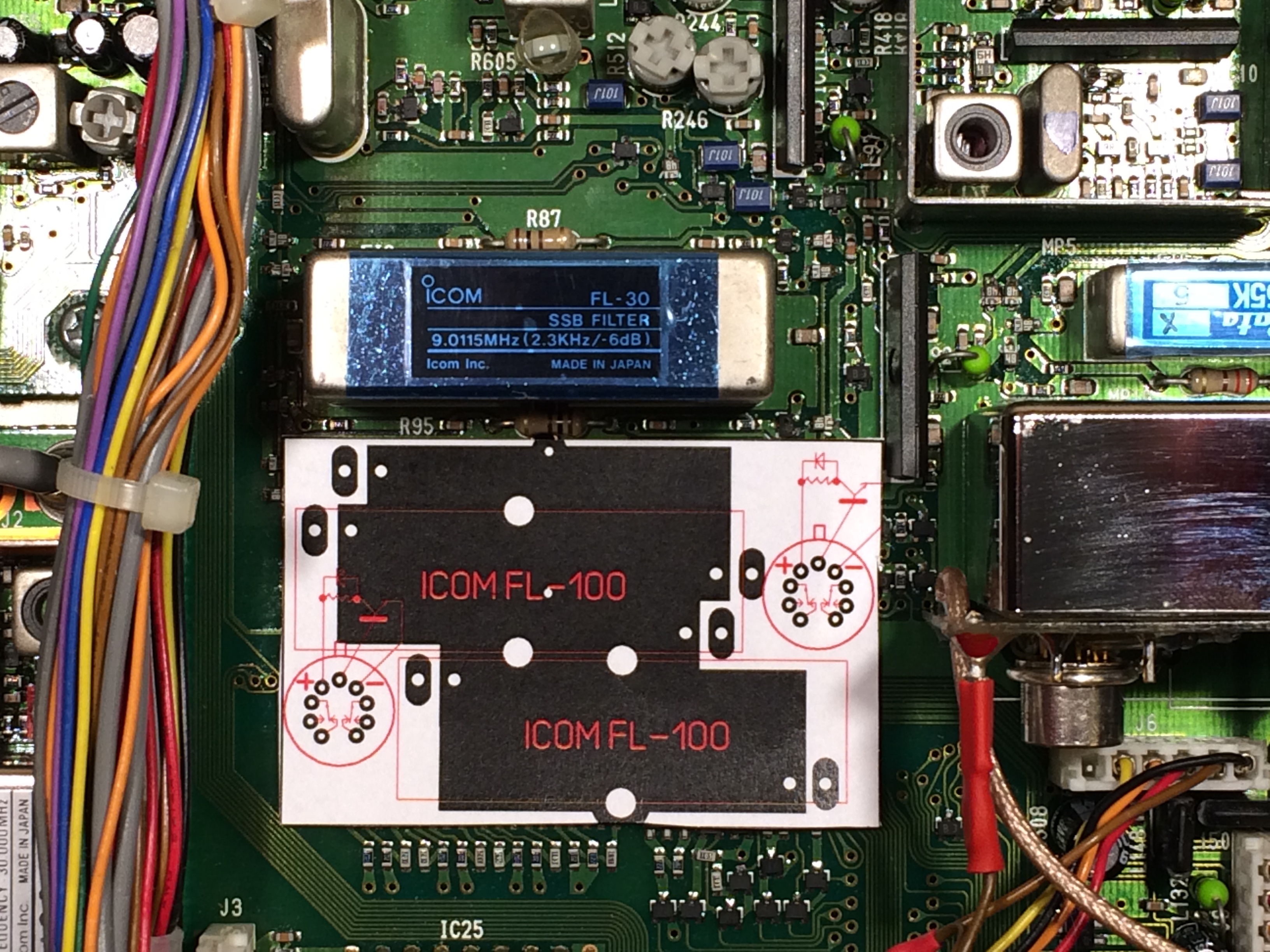
The developing and prototyping phase. The paper showing PCB is printed out of the SprintLayout software.

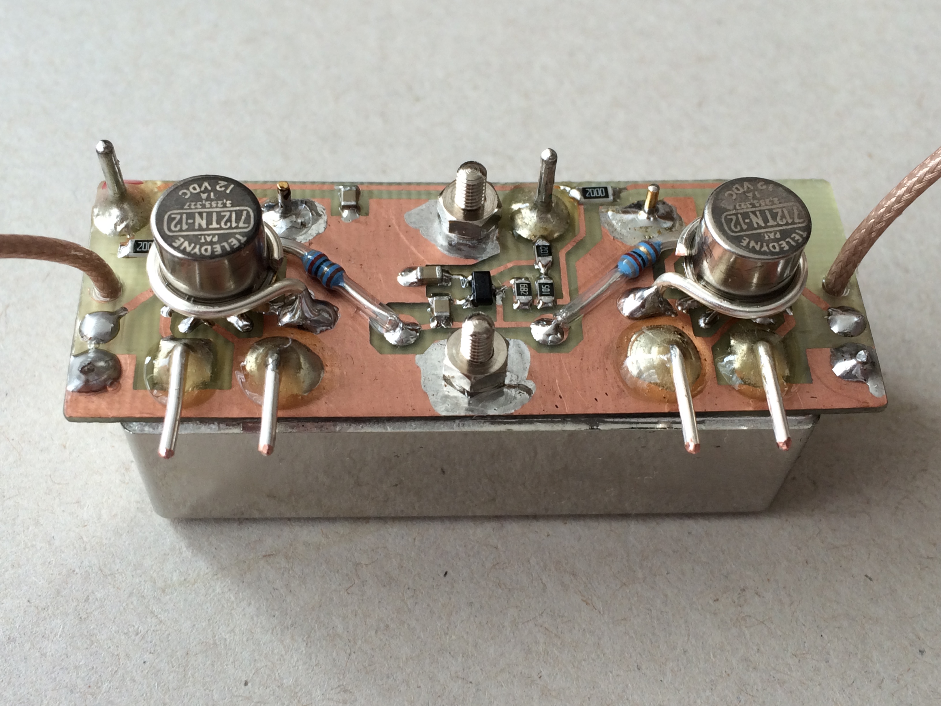
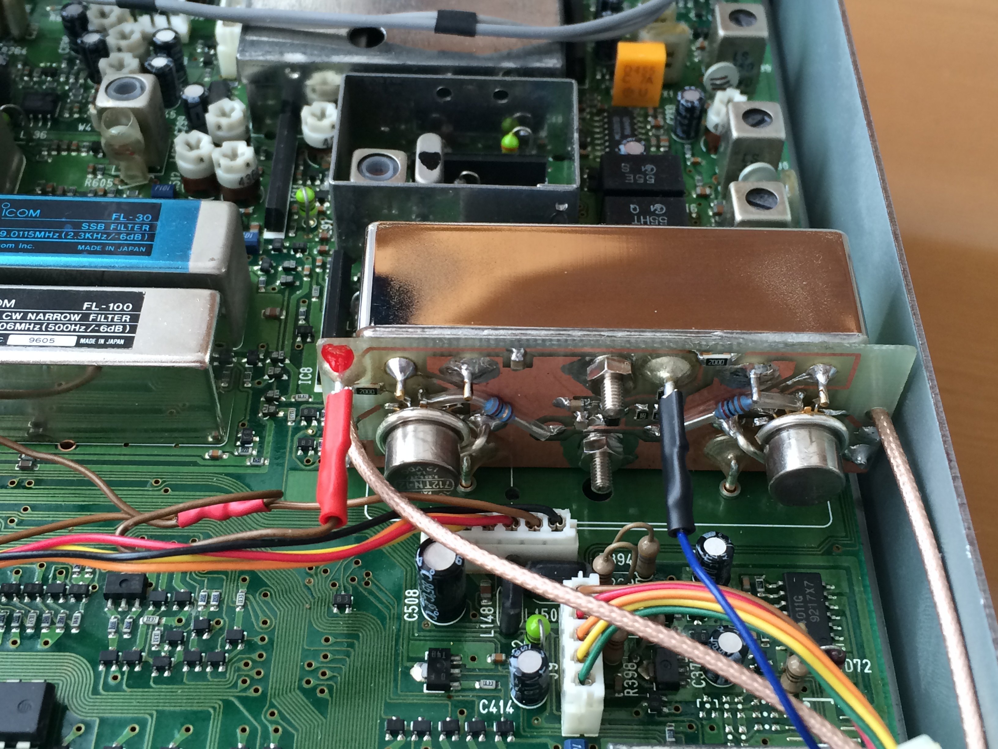
The additional PCB to carry the Teledyne ralays. Mind that cases of the relays are grounded.
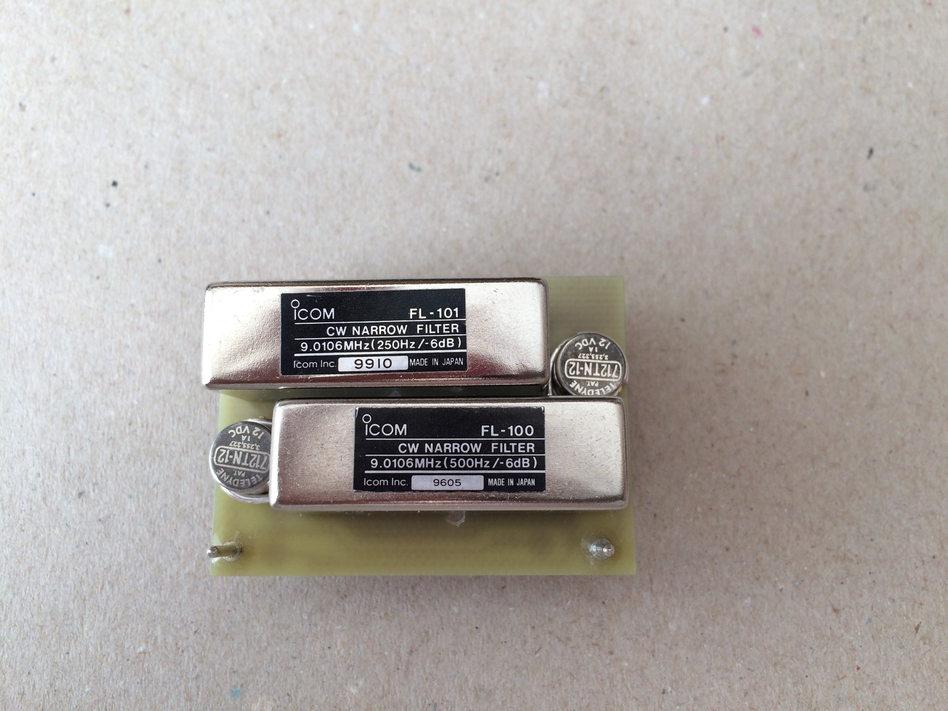
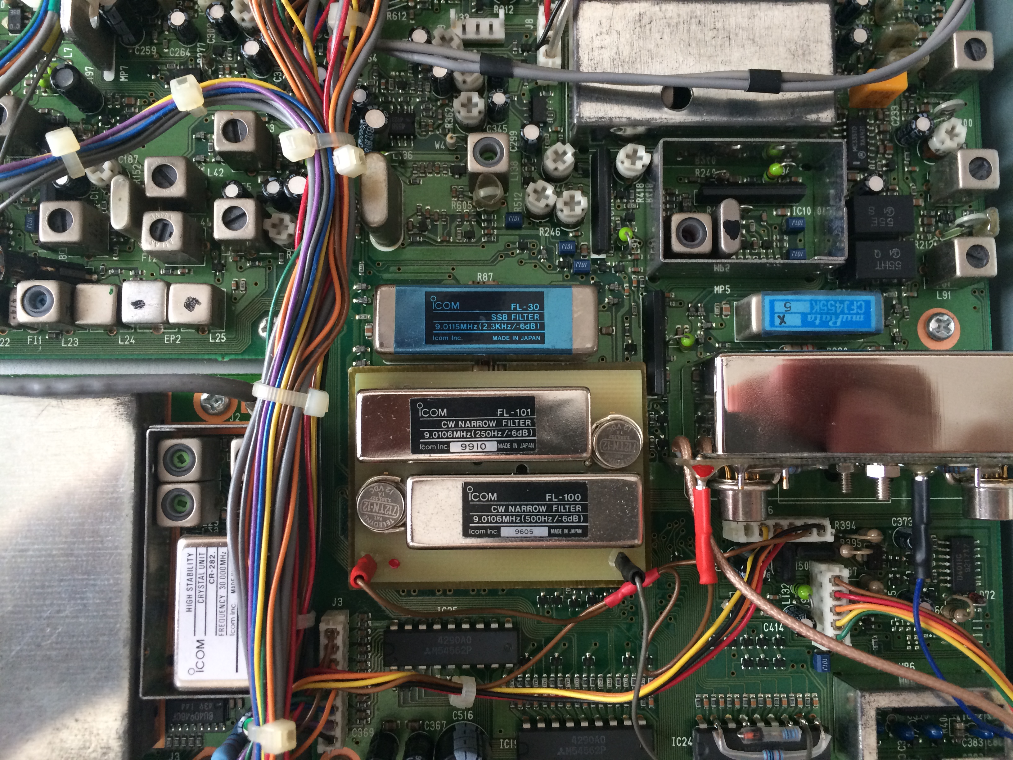
The PCB fitted with the two Teledyne relays and Icom filters FL-100, FL-101.
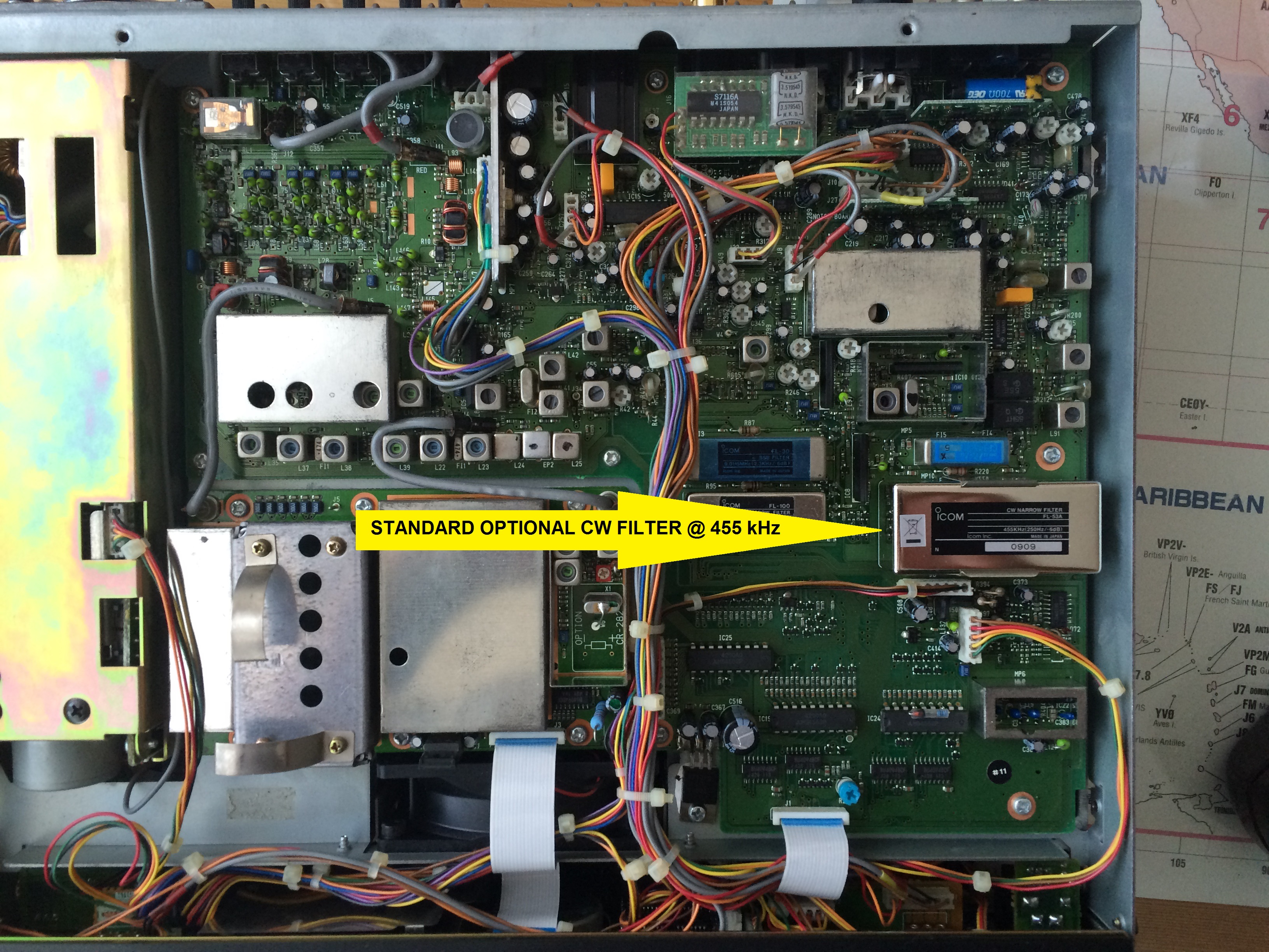
The PCB inserted into the slot for the optional 9MHz CW filter. The red outlet (brown wire) provides the supply voltage of 13.8V, the black outlet (black wire) is the controlling signal for the relays. The PCB is inserted into the slot for the optional filter.