Icom IC-736

More filters at 455 kHz IF

Having done the filter selection modification I got two reasonable widths for CW mode, 500Hz and 250Hz. Yet, an excellent Inrad 125Hz CW filter for 455kHz still idled in my drawer.
The following modification enables to use 3 different widths for CW mode: 500Hz, 250Hz and 125Hz.
The 455kHz signal is switched by two TELEDYNE relays type 712TN-12. Mind that these have an extra driving transistor integrated in its case.
As there is no spare control on the front panel to control it. I decided to make use of COMP button. It nicely toggles on and off and it has no meaning for CW mode. To control the relays that switch the filters I use the signal marked as LCOM in the documentation. In fact it is a controlling voltage for a LED that is hidden in the COMP button on the front panel.
There is a small FET transistor on the switching board to invert the logic. The purpose of it is: a) relays are off if the 250Hz width is selected (as it will occur more often), b) width 250Hz is selected if the LCOM sensing (blue wire) is disconnected.

The final logic looks like this:

Mode COMP OFF COMP ON
CW 500Hz 500Hz
CW-N 250Hz 125Hz

Schematics


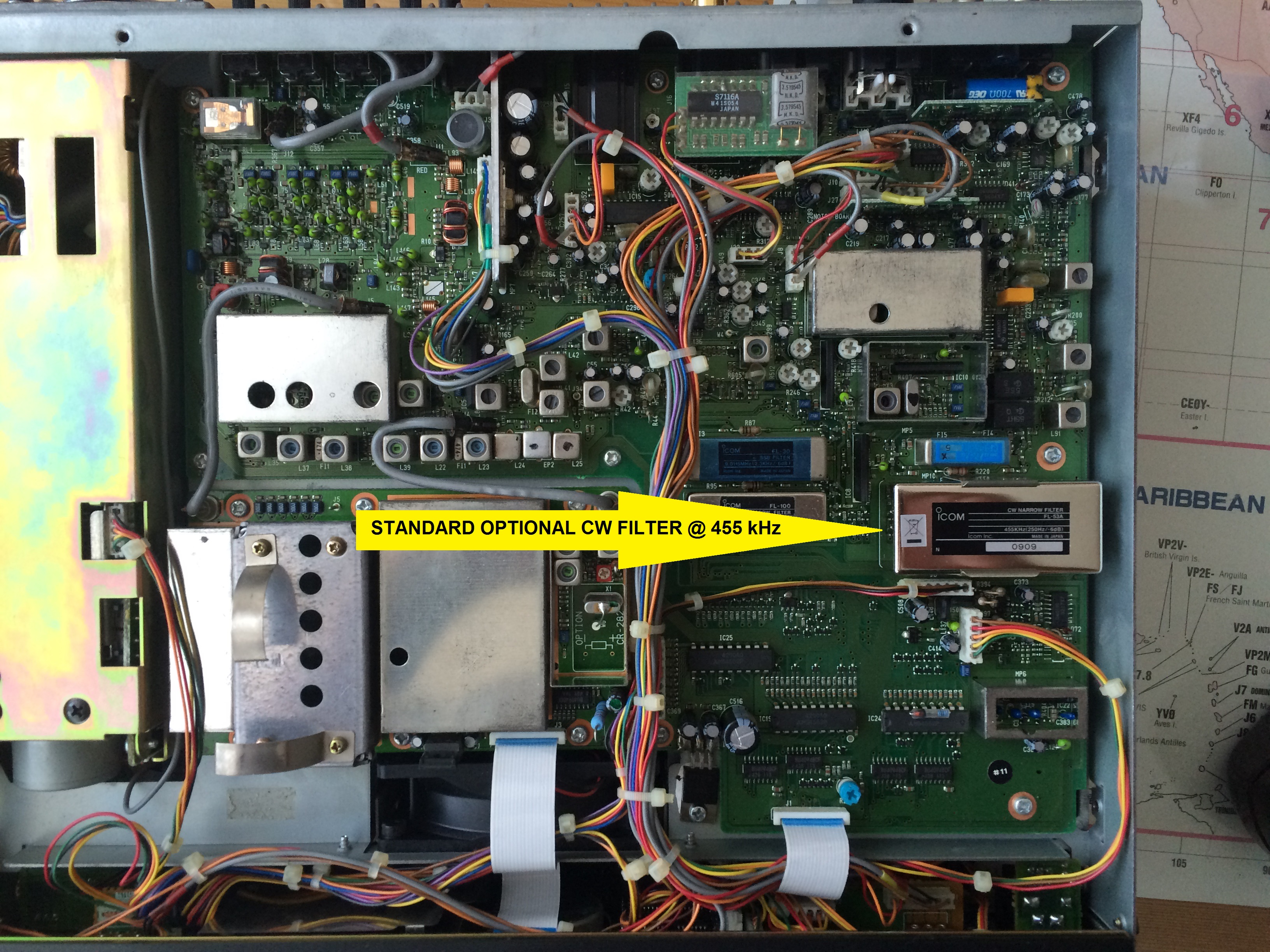
The standard position of the optional CW filter (455kHz) on the MAIN board. It can be FL-52A or FL-53A.

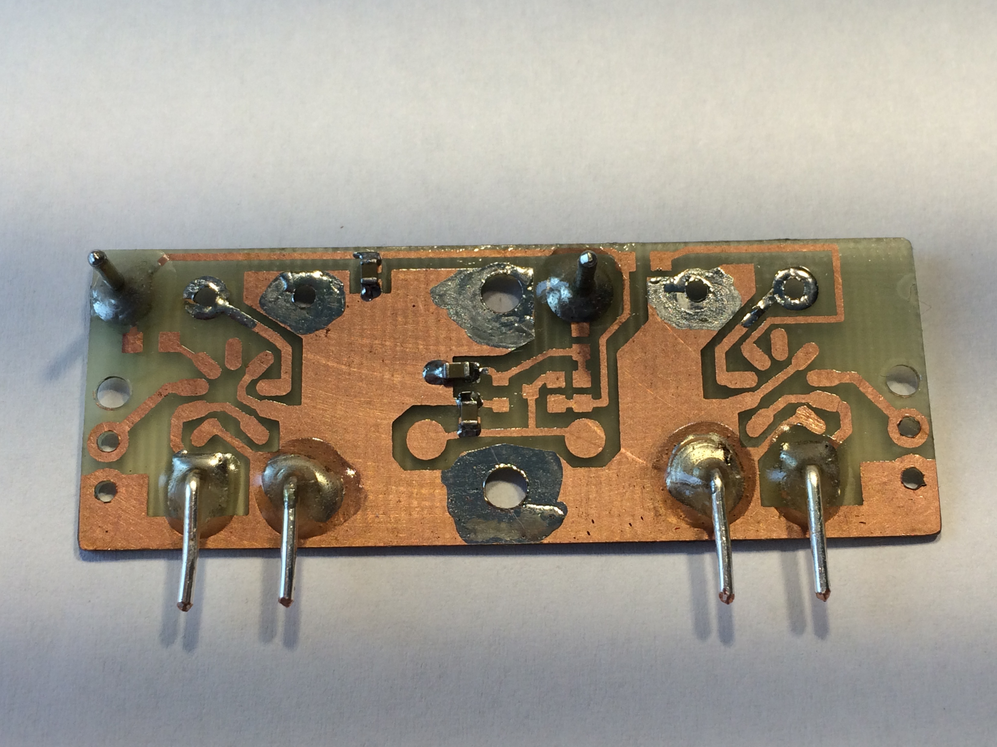
The new PCB to provide swtiching between two filters.

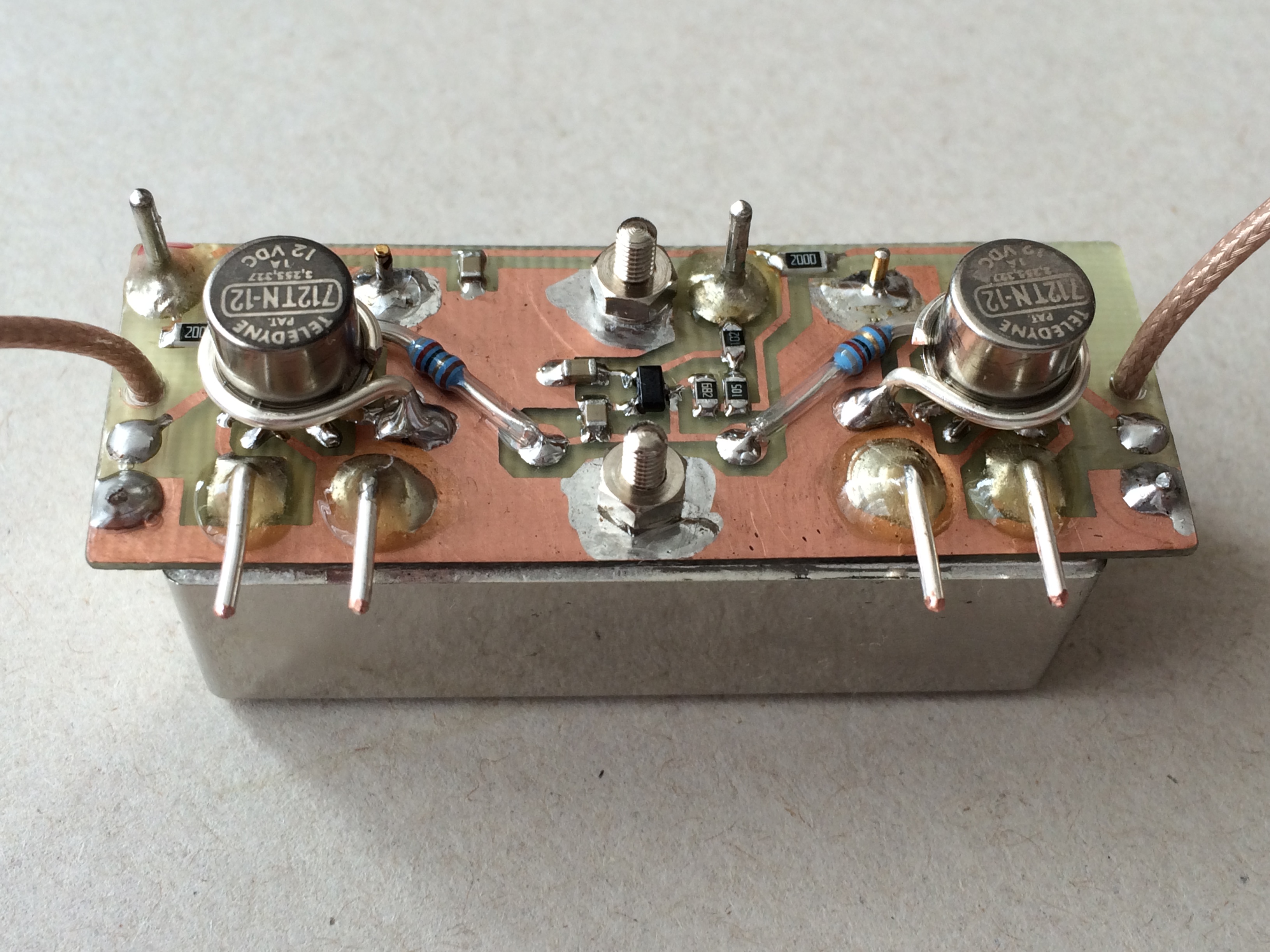
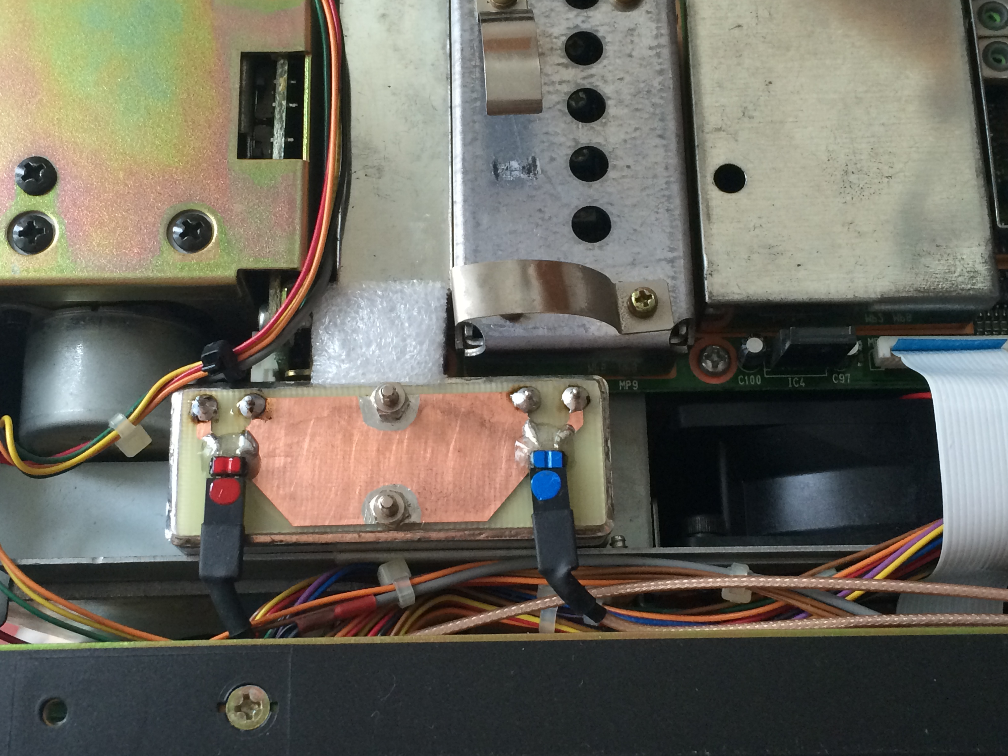
The PCB fitted with all parts including the two Teledyne relays. The PCB is mounted on the Icom FL-53A filter.

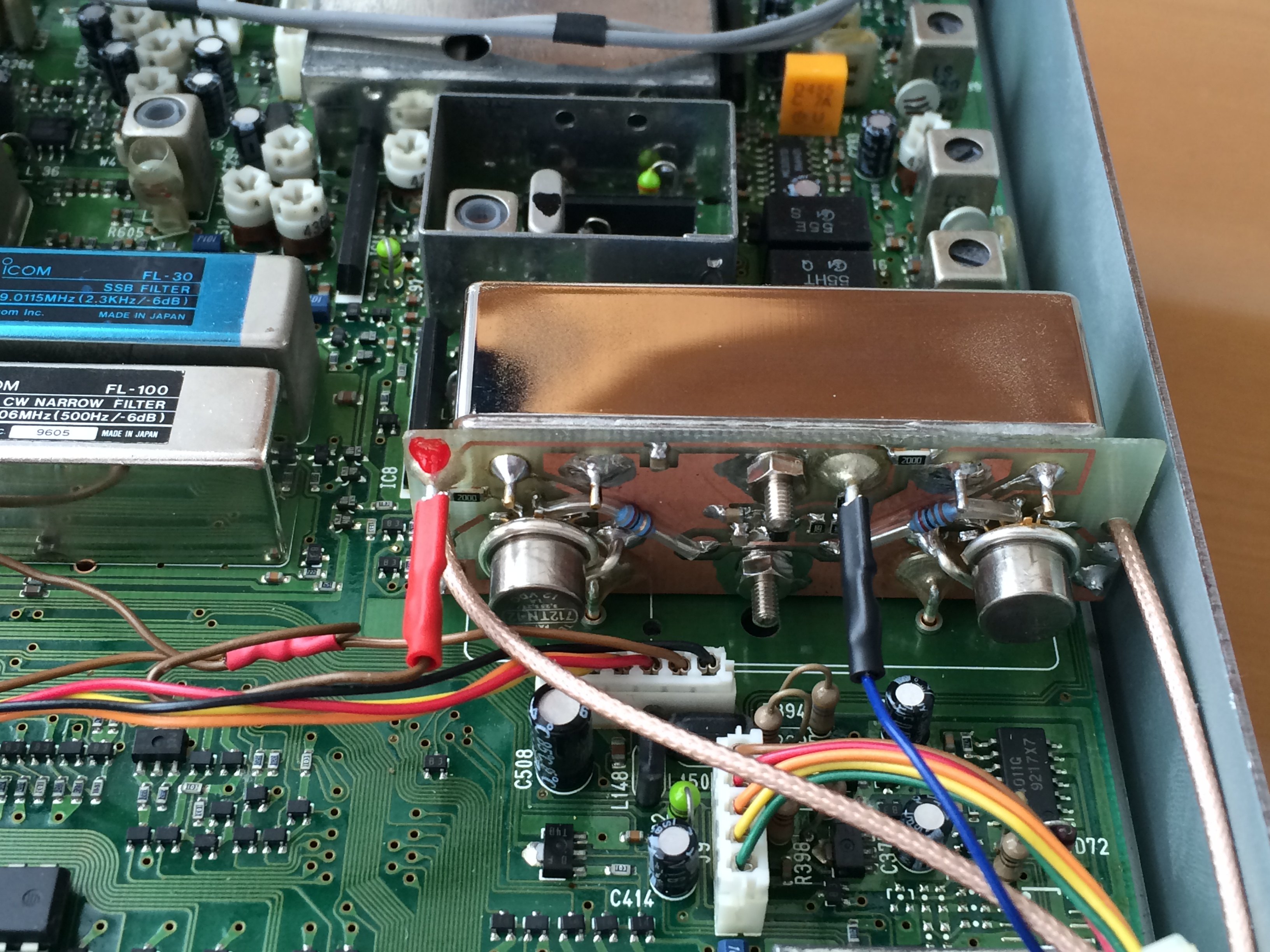
The PCB inserted into the slot for the optional 455kHz CW filter. The red outlet provides the supply voltage of 13.8V, the black outlet (blue wire) is the controlling signal (LCOM). Two tiny PTFE coaxial cables lead to the other crystal filter.

The Inrad CW filter (125Hz @ 455kHz) put to a suitable free space (the cable holder had to be removed there). There is an interfacing PCB on the top of the filter with the two pinheaders as connectors.

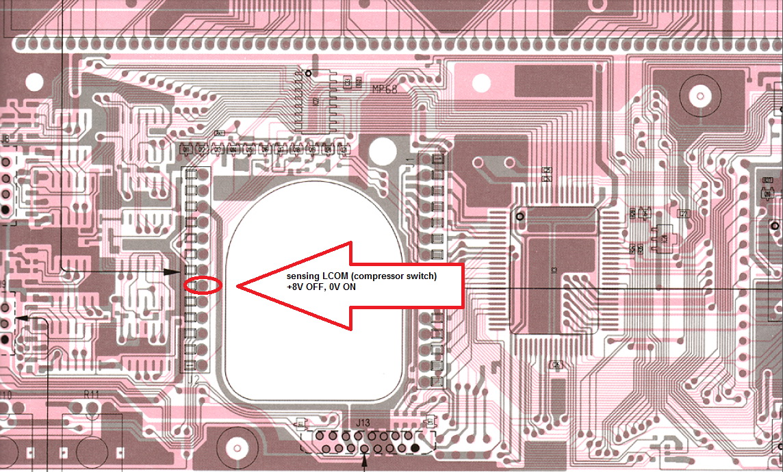
Getting LCOM signal from the LOGIC board. In fact, it is the controlling signal for the LED indicating that COMP is on.

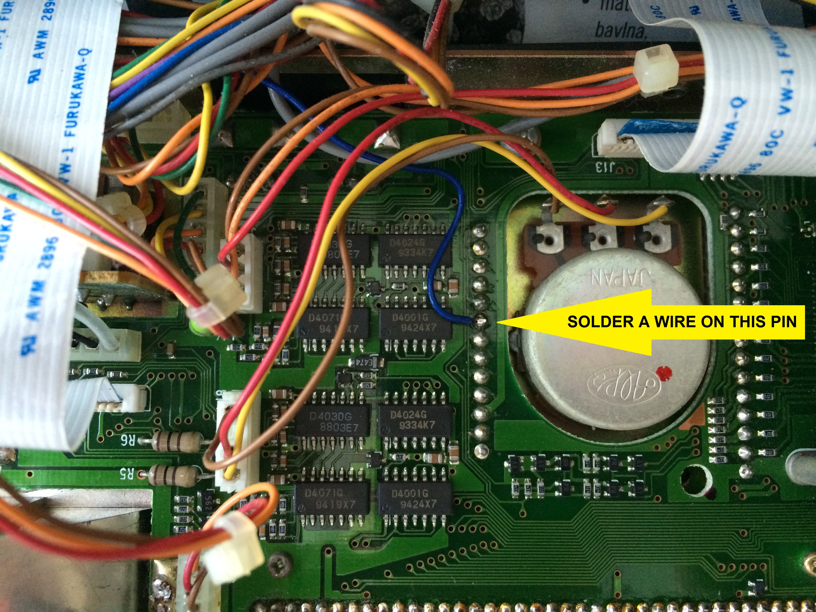
Getting LCOM signal from the LOGIC board. It is one of the pins of the pinheader close to the rotary encoder. It is easy to access if the front part of the TCVR is cast down.

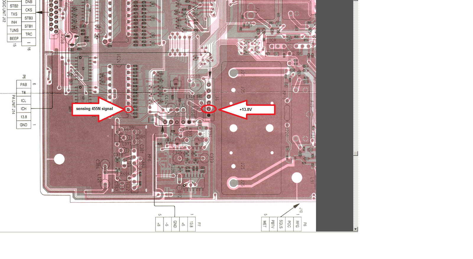
This is the pin the supplying voltage 13.8V is taken from. It is easy to cut the wire leading here and make more branches of it.


<<< Main Page