Icom IC-736
Filter selection for CW / CW-N
Before I purchased this TCVR I saw
it could select CW and CW-N. I also saw that it had two positions
for optional CW filters. One at 9MHz IF and one at 455kHz IF.
I thought fine, I would insert 500Hz wide filter at 9MHz and
250Hz wide filter at 455kHz. I would set it up in the way that
for CW it would use 500Hz width and for CW-N it would use 250Hz
width.
What was my surprise this can't be set! You can set whatever
filter combination for CW-N in the system menu but for CW the
signal will always go through the fixed SSB filters. Jeez, are
they serious? Why do they spoil such a good rig with a nonsense
like that? Simple jumpers on the PCB would be better...
Luckily this can be easily modified.
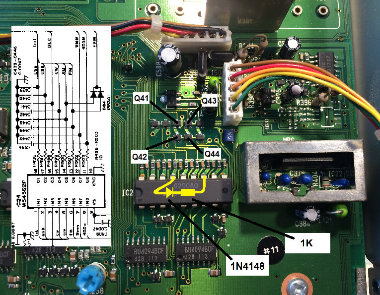
Solder a diode and resistor in series onto IC24 on the MAIN board as the image shows.
For the optional filter at 9
MHz to be ON for both CW and CW-N, solder it between the
pins 12 and 15 (as the image shows).
For the optional filter at 455 kHz to be ON for
both CW and CW-N, solder it between the pins 11 and 15.
See the realization. Both parts were placed into the silicon tubing and soldered directly on pins of the IC: