Encoder Divider
After I replaced a shameful mechanical rotary encoder in my beloved IC-740 I felt a need to slow down the tuning speed. I thought I would just spend a few moments with Google to find the proper schematics. I was not lucky enough to find any. Strange, isn't it? There was no other option that to invent it myself.
At the beginning I simply made two
separate dividers realized by J-K flip-flops (CMOS 4013). Each
flip-flop for each channel of the rotary encoder. What a mistake!
Yes, it slowed down the tuning by two, however, it had two major
flaws:
- the tuning direction was random. Even worse, when I changed
direction of rotation of the tuning knob it kept the same sense
of frequency change. Totally useless.
- the phase shift of the two channels was not 90 degrees but only
45 degrees. It doesn't have necessarily to be a problem as most
of the logic that could follow such a divider detects edges
rather then length of the pulses. It is however not correct.
I realized that the gadget can't be that simple. At lest it must
process both channels at the same time, not independently.
Explanation for the schematics:
XOR1 - creates a short positive
pulse for each edge of A channel
NAND5 - simply negates the pulses from B channel
AND1, AND2 - act as a switch. If channel B is HIGH, then short
positive pulse from XOR1 is sent to FLIPFLOP1, if it is LOW then
the pulse is sent to FLIPFLOP2.
FLIPFLOP1, FLIPFLOP2 - do the division by two for the both
channels.
NAND1 - after the divider is powered on C1 slowly charges through
R1. After a few hundreds of milliseconds the gate output changes
to LOW sending a short negative pulse to flip-flop realized by
NAND3, NAND4.
NAND3, NAND4 - a flip-flop. Shortly after the device is powered
on it receives reset pulse from NAND1. The flip-flop resets
putting LOW on the output of NAND3. Since this moment the
flip-flop waits for the user to start to rotate the tuning knob.
NAND2 - compares logical value of both channels of the rotary
encoder. As soon as both channels are HIGH, the LOW output of the
gate sets flip-flop made of NAND3, NAND4. Since this moment the
state of the flip-flop never changes. A short positive pulse is
sent to Reset input of both FLIPFLOP1, FLIPFLOP2. Since this
moment the divider is synchronized and will correctly create
pulses regardles the way you fiddle with the tuning knob.
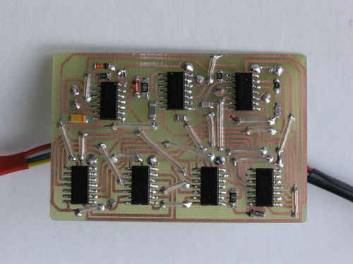
The picture below shows the realized divider (more complex than what the schematics above shows). The divider divides the pulses from the rotary encoder either by 2 or by 4, switchable. The division rate is changed by selected tuning step on IC-740. For 10 Hz step it divides by 2, for the others by 4. This way it yields about 2.4 kHz span per one knob revolution when 10 Hz is selected, and about 12 kHz when 100 Hz is selected. This exactly fits my needs, for both CW and SSB.