Power Amplifier
for 136kHz 1kW
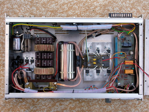
The bottom
cover removed. The design is somehow up-side-down. It is because
the power FETs are mounted on the heat-sink which is on the top
of the box.
There is the antenna relay (top left corner), LPF 140kHz (two
large toroids), the main output transformer (pile of toroid cores
painted to white), six IRF540 transistors (mounted on the
aluminium blocks), blocking condensers (blue ones) and the PCB
with controlling logic.
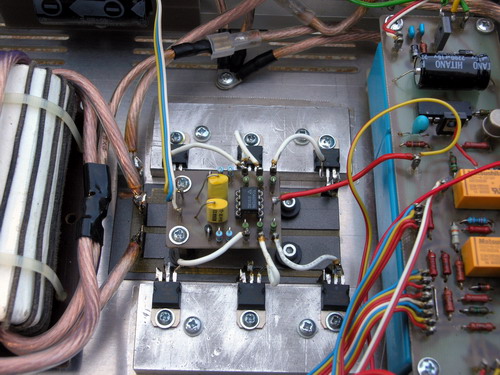
The
power FETs are mounted on aluminium blocks. The blocks are
mounted on the top cover with a large heat-sink. There are thin
sheets of mica between the blocks and the top cover. The FETs are
driven by TC4426.
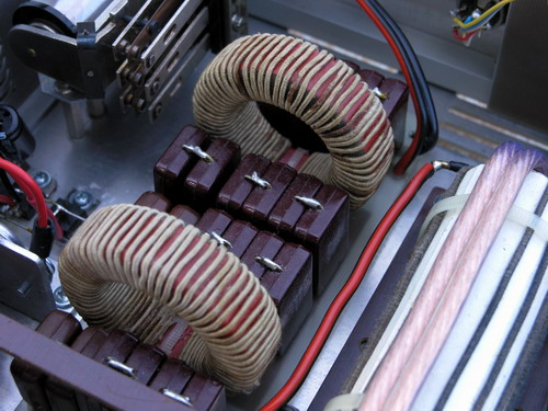
Low
pass filter consists of two large Amidon toroids and series of
mica condensers.
The
PA in the box (the front panel is not fully finished).
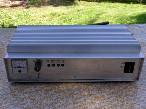
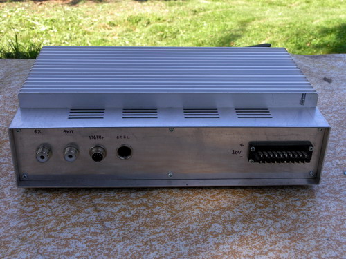
The
PA from the rear (the rear panel is not fully finished).
<<< Main Page