Icom IC-740
Additional roofing filter
The first IF is on 39.730 MHz.
There are two rather wide 2-pole filters there. I didn't find any
specs but it looks they are about 12 kHz wide, or so.
In fact, the 1st IF is not fixed but floating. Any filter must be
designed with the center at 39.731 MHz and must be 1 kHz wider.
If there was an extremely strong signal on the band within the bandwidth of these filters the second mixer suffered from overloading. I decided to ease the situation with an extra crystal filter inserted right before the second mixer.
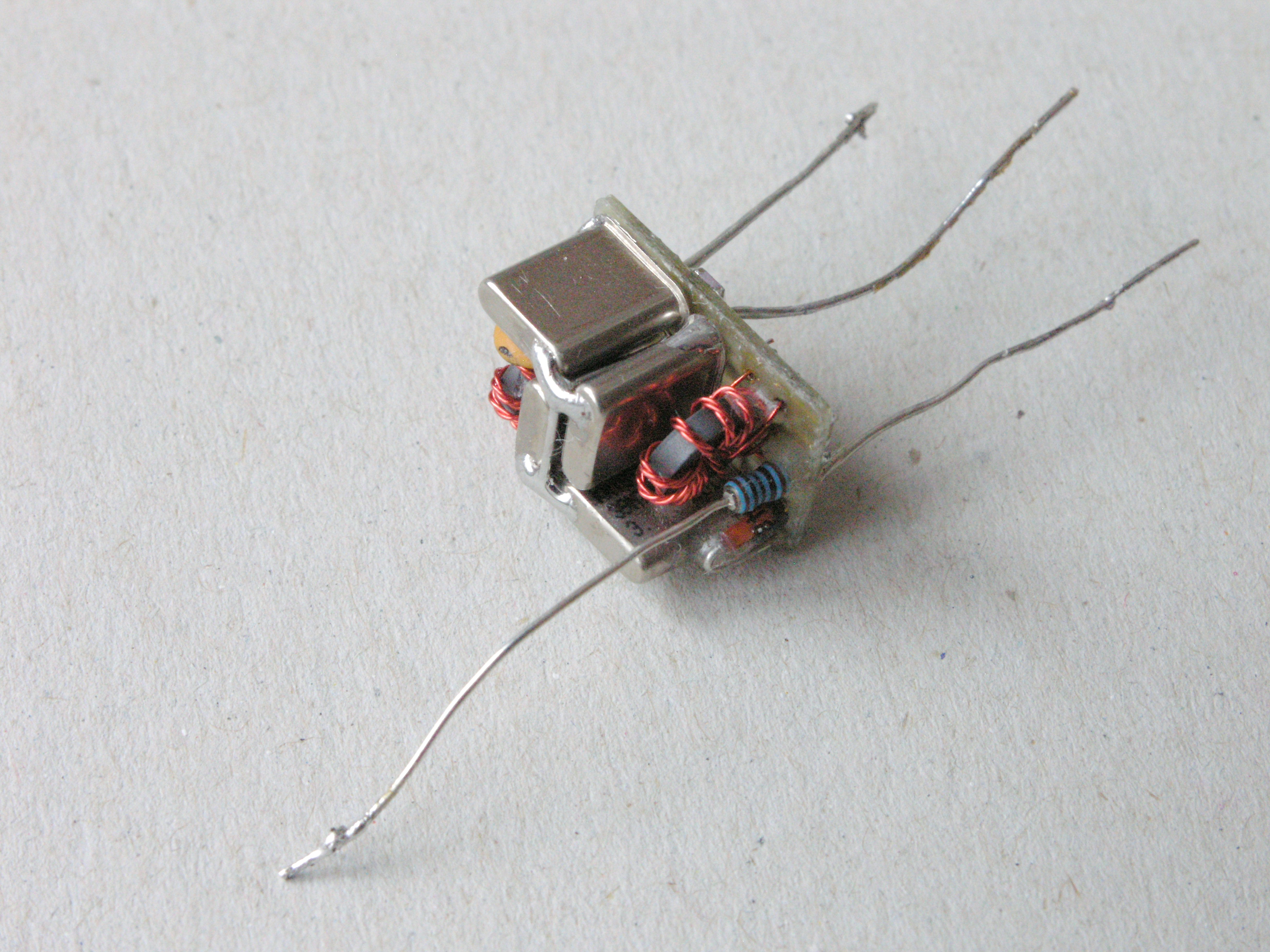
The filter is of McCoy layout and
consists of 4 crystals. They work on the third O/T.
I developed the following schematics:
Schematics
The filter is made on a small PCB:
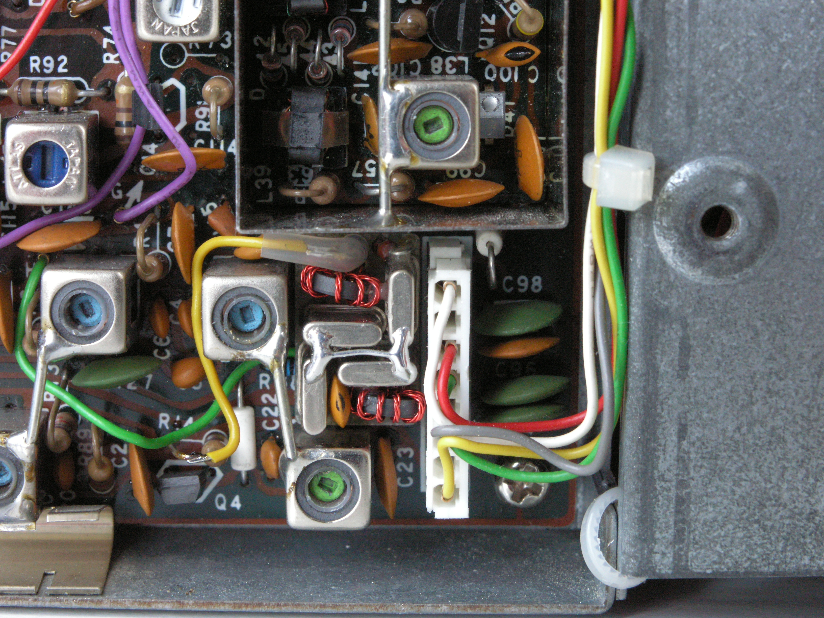
At the end if the 1st IF amplifier
(RF board) there is a switching diode (D4) removed and the filter
is inserted as the following image shows:
Deployment
This way the filter operates only during reception. It has no
impact on transmitting.
This is the RF board with the
additional ffilter installed:
I tested the filter with a
home-made noise generator and the HDSDR software running on
FUNcube Dongle Pro+.
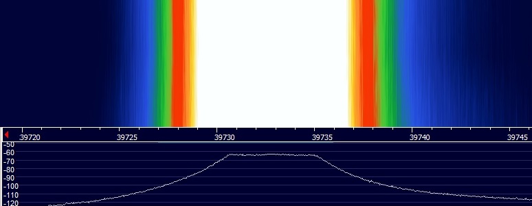
The curve I got was quite promissing during the prototyping
stage:
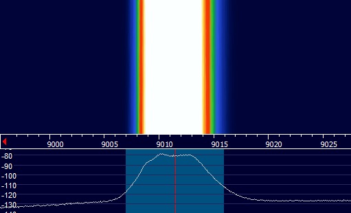
This is the curve of the final
implementation. Here the filter was measured on 9 MHz IF (9 011.5
kHz). This means the curve includes impact of the other parts
including the mixer. Some little ripple occured in the passband.
However, it shows that attenuation of at least 40 dB is obtained
just about 5 kHz off the center. The center freq exactly matches
and the bandwidth is as desired (about 3.5 kHz):