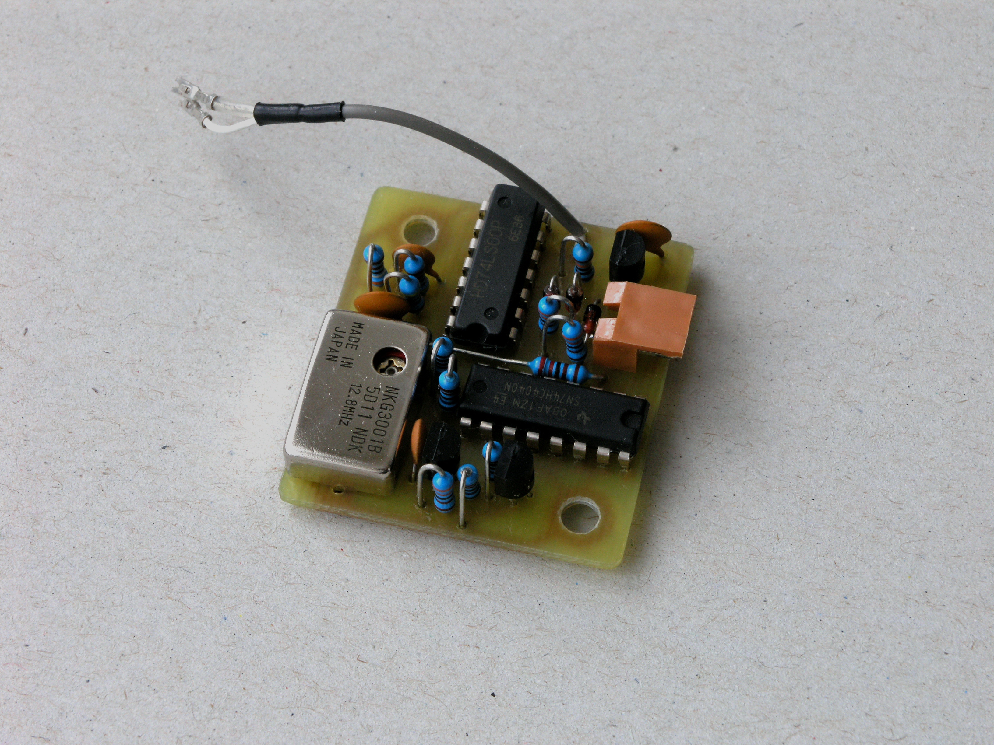
The sinus signal from VC-TCXO is converted to TTL levels by a Schmitt trigger, then divided by 74HC4040 ripple counter, then switched by 74LS00.
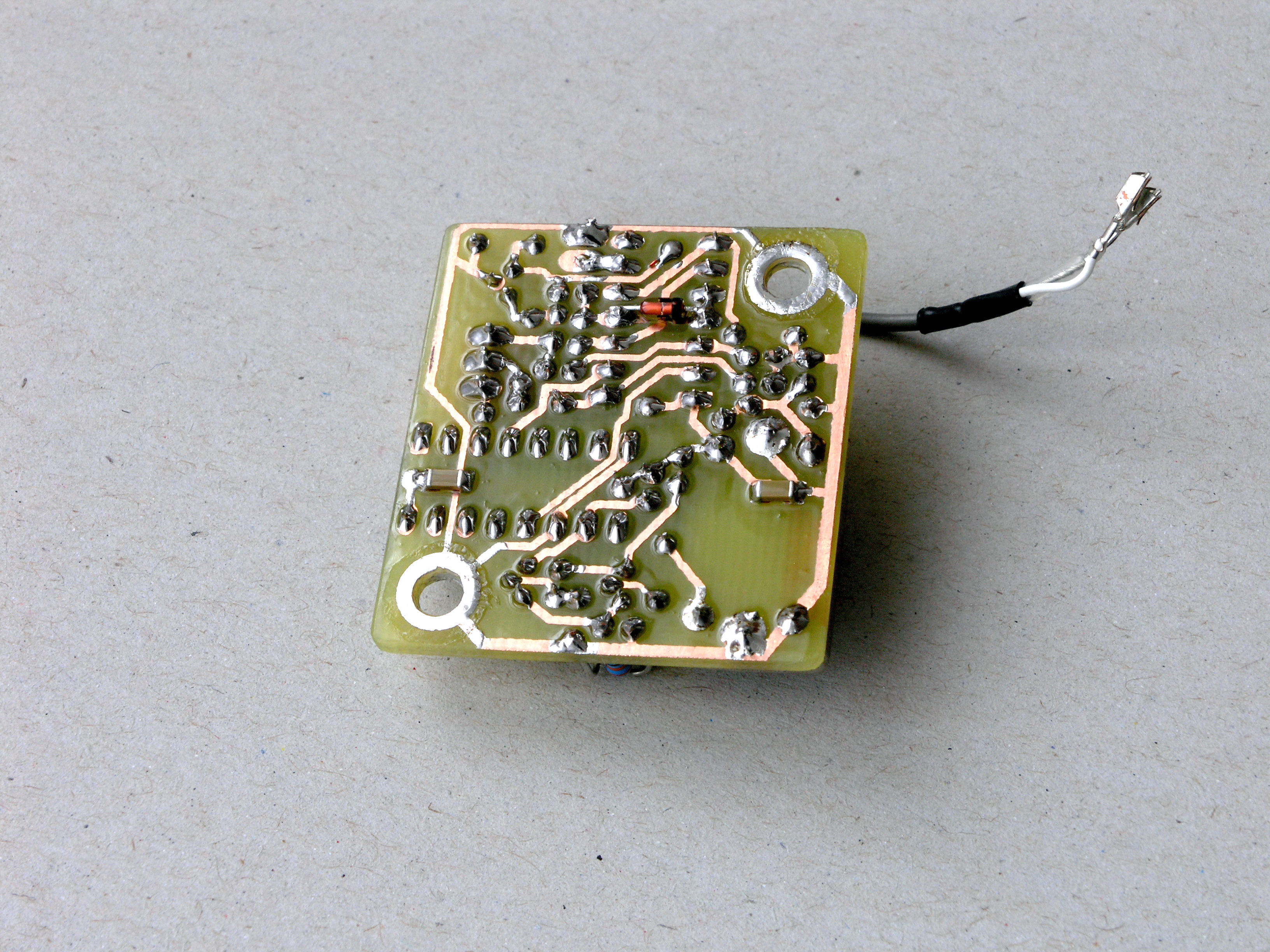
The bottom view of the unit.
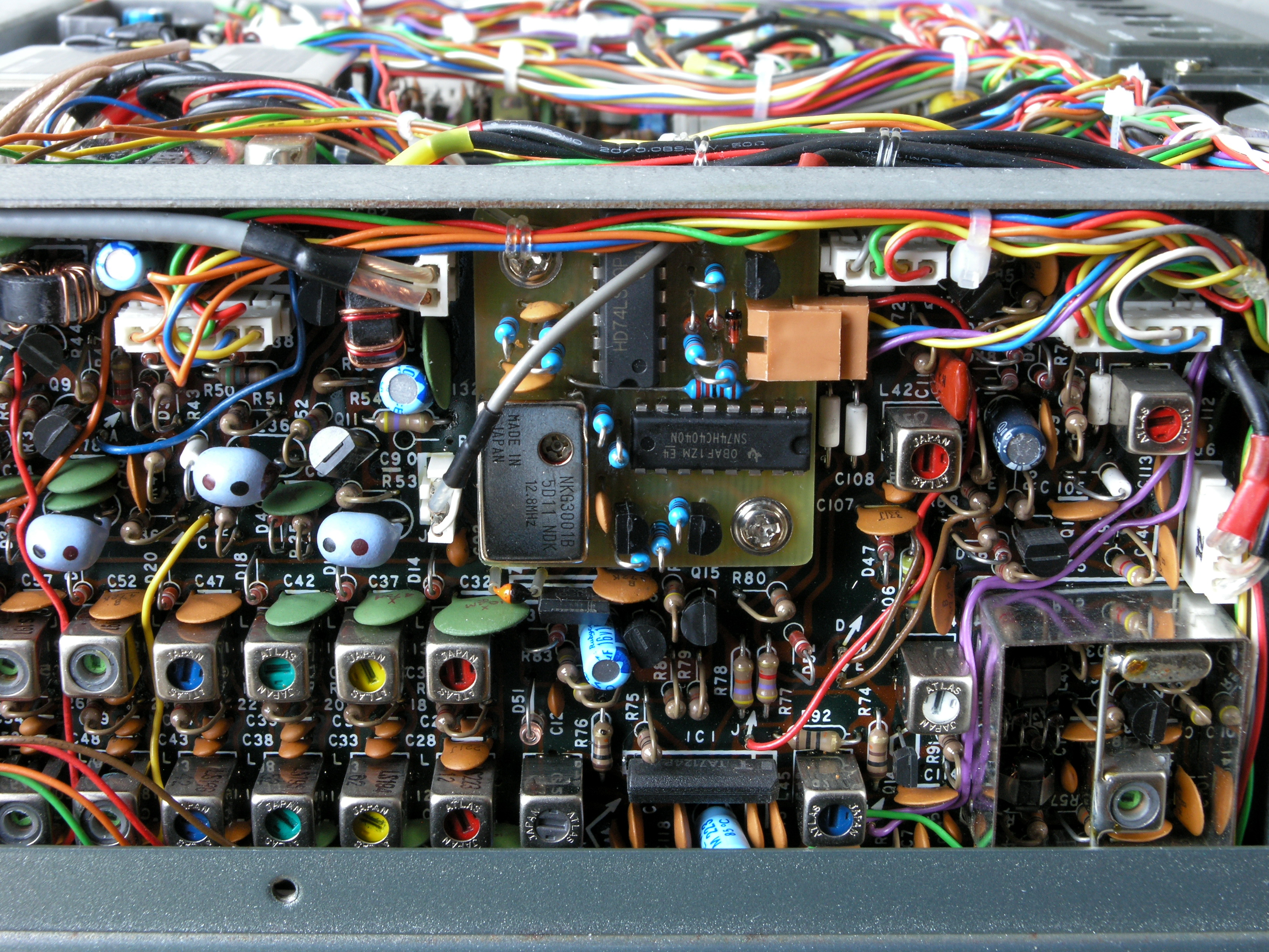
The unit mounted at its standard position on the RF BOARD.
Icom IC-740
Marker Unit
(inspired by Icom IC-EX241)
It is almost impossible to get
this optional module todays. I decided to make my own one.
The original Icom module is controlled by a simple 3.2 MHz
crystal (in HC49/U). The below module is controlled by 12.8 MHz
VC-TCXO.
The function is quite identical as the original one but it is
more stable.
The sinus signal from VC-TCXO is converted to TTL levels by a Schmitt trigger, then divided by 74HC4040 ripple counter, then switched by 74LS00. |
The bottom view of the unit. |
The unit mounted at its standard position on the RF BOARD. |
PCB layout (top view):
Green: bottom cuprum
Blue: non-isolated wires under the ICs. They must be placed
before ICs are soldered. They are mounted on the top side of PCB.
Mind the three parts mounted on the bottom side. There are two SMD condensers there and one 1N4148 diode. The diode is soldered between pins 4 and 11 of the 74LS00.