RTF EKD 300 RX Modifications
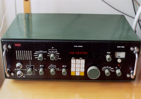
This is how the RX
looks (after some mechanical modifications):
The EKD300 receivers (also EKD100, EKD500 and EKD700) were manufactured in VEB Funkwerk Koepenick (RFT) (former DDR) around 1984. Even that the design is a bit out of date, the receiver proved as an excellent on LF, mainly after some mods. The only disadvantage is the sizes and weight of the device (unfortunately this cannot be modified). All the changes are done with an affort to keep the original functionality whereever it was possible.
The below changes are references to "Reparaturanleitung, Empfaenger EKD, Typereihen EKD100 und EKD300" (Service Manual).
1. Faster AGC
The original
behaviour of AGC is very unpleasant. The short but strong pulses
(QRN on 136 kHz) don't change the level and go in full strength
to the AF output (all the crashes are in your headphones). If a
pulse exceeds a threshold, it lowers the AGC level, but the
recovery time is very long (you miss a part of a CW character).
The following modification makes the AGC much faster, both
response time and recovery time.
Referring
to page 131 (bild 82, diagram) and page 130 (bild 81, PCB):
1. C44 10uF removed
2. C09 4.7uF replaced with 1.1uF (tantalic)
3. W27 240ohm bridged (0 ohm)
4. C10 4.7nF removed
5. C08 100uF replaced with 15uF/15V
Referring
to page 125 (bild 78)
(applies to LSB mode only, meaningless for CW modes):
1. C12 0.22uF replaced with 10uF
Referring
to "einschub"
(wiring diagram)
1. C04 0.47uF remove (this is a condenser from pins #2
and #4 to ground on the Sch02/1 - the switch of AGC on the front
panel)
2. CW-R (BFO as USB)
The original CW (A1)
BFO is tunable and it is LSB (which a standard with professional
RX's). This is a big trouble for 136 kHz band because there is
DCF39, a very strong professional station, on 138.830 kHz.
Imagine you listen on 136.830 kHz (just center of the CW
activity) with a beat of 1000 Hz. The "other side" then
comes to 183.830 which should not get thru the stop band of the
filter. Theoretically. Practically DCF39 is so strong (599 + 70
dB in OK land) that you will always hear the bothering DCF39
station. The below modification enables to switch to USB so that
the unwanted beat from DCF39 is about 4 kHz which doesn't bother
so much and also can be easily filtered out (see LPF below).
The original BFO Xtal was taken
out and in its place there is a new subboard that carries the
orginal Xtal (mind that it is common for SSB modes therefore it
cannot be simply exchanged), a new Xtal for CW-R (custom made
200.800 kHz) and a reed relay that switches between them:
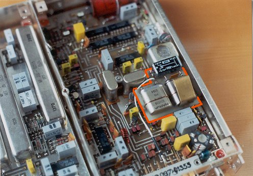
See the original
schematics (page 119, bild 74), the PCB (page 118, bild 73) and see the modified circuitry.
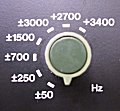
There is a little trick to switch to USB with an existing BFO
tune potentiometer. The relay is switched with the voltage that
is used for BFO tuning. It works in the following way. When the
BFO knob is rotated fully counter-clock-wise the relay switches
to CW-R (i.e. to the new Xtal with fixed beat 800 Hz). When it is
turned slighly clock-wise
the relay switches to CW (LSB)
(to the lowest beat, abt 400 Hz), and if it is turned further
clock-wise, it tunes from lowest tone to highest tone.
Referring to "einschub" (wiring diagram)
1. W09 7.5kohm replaced with 3x silicon diode in parallel
(W09 is in parallel with the BFO tuning potentiometer. It is to
be found on the front panel)
2. insert 8.2kohm rezistor between grounded pin of W11 (BFO tune
pot) and ground. This decreases maximum BFO beat (tone) to about
1300Hz (because LPF, see the following).
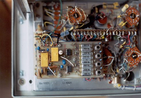
3. AF LPF and
Narrow Filter for CW
The LPF suppresses
tones higher than about 1300 Hz which eliminates unwanted residue
DCF39 signal. The 40Hz wide CW filter is necessary for serious CW
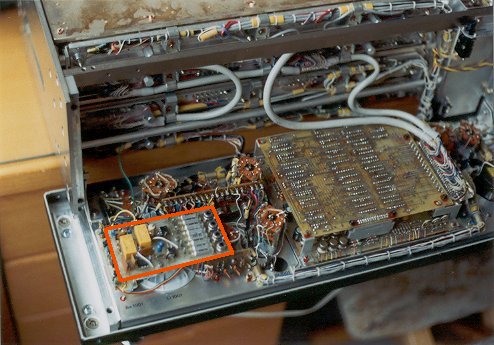
work on 136kHz as experience shows. The
filter PCB is placed above the speaker (the NiCd back-up battery
was removed, being good for nothing):
See the detail of
the PCB. See the schematic
diagram of the filters
(both filters are on the same board).
The filter is inserted in front of the AF gain potentiometer (W05 on "einschub", filter is inserted at the joint with C02) which ensures that level going thru the filter is about the same and doesn't change with change of AF gain.
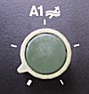
The LPF filter is in
on when the mode selection knob selects A1 mode. The narrow CW
filter is turned on when A1 mode is selected and the knob
switching filters is turn counter-clock-wise beyond its limit
(the switch had to be mechanically modified but it wasn't
necessary to dismantle the front panel):
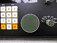
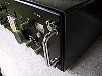
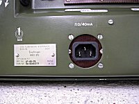
Some mechanical
modifications were also made. There is a new big tuning knob, new
smaller handrails and there is a mains plug on the rear panel
(instead of RTTY plug):
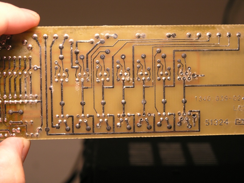
4.
Replacement of Frequency Display LEDs
In the original
receiver the VQB71 modules were used. These 7-segment LED modules
seem to be quite unreliable. In some time 3 modules went wrong
out of the total 7. Therefore I decided to replace them all as a
long-term solution. The original VQB71 modules were desoldered
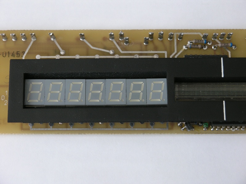
and replaced by SA39-11EWA modules from Kingbright.
Short non-isolated wires were soldered to make connections to
original holes in the PCB:

Also the black cover needed a little modification in order the
new LED modules fit into it.
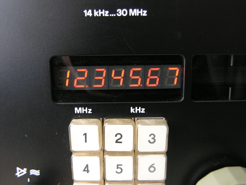
This is the new look of the display.